
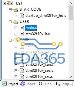
基于stm32 F401 discovery 库函数点亮LED 3,4,5,6
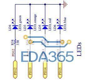
分别对应的GPIO为PD12,PD13,PD14,PD15
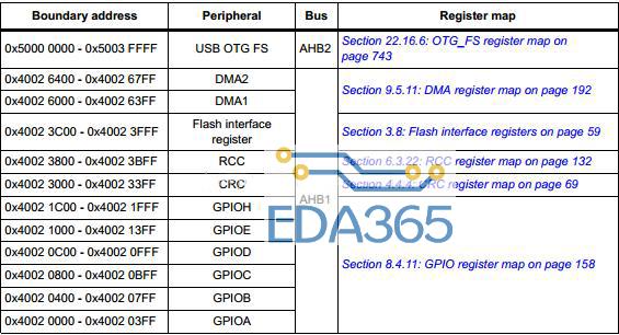
#define PERIPH_BASE ((uint32_t)0x40000000) /*!< Peripheral base address in the aliasregion
#define APB1PERIPH_BASE PERIPH_BASE
#define APB2PERIPH_BASE (PERIPH_BASE + 0x00010000)
#define AHB1PERIPH_BASE (PERIPH_BASE + 0x00020000)
#define AHB2PERIPH_BASE (PERIPH_BASE + 0x10000000)
GPIOD在AHB1中,通过
#define GPIOD_BASE (AHB1PERIPH_BASE + 0x0C00)
/* Private functions ---------------------------------------------------------*/
/**
* @brief Main program
* @param None
* @retval None
*/
int main(void)
{
/*!
this is done through SystemInit() function which is called from startup
file (startup_stm32f401xx.s) before to branch to application main.
To reconfigure the default setting of SystemInit() function, refer to
system_stm32f4xx.c file
*/
GPIO_InitTypeDef GPIO_InitStructure;
/* GPIOD Periph clock enable */
RCC_AHB1PeriphClockCmd(RCC_AHB1Periph_GPIOD, ENABLE);
/* Configure PD12, PD13, PD14 and PD15 in output pushpull mode */
GPIO_InitStructure.GPIO_Pin = GPIO_Pin_12 | GPIO_Pin_13| GPIO_Pin_14| GPIO_Pin_15;
GPIO_InitStructure.GPIO_Mode = GPIO_Mode_OUT;
GPIO_InitStructure.GPIO_OType = GPIO_OType_PP;
GPIO_InitStructure.GPIO_Speed = GPIO_Speed_100MHz;
GPIO_InitStructure.GPIO_PuPd = GPIO_PuPd_NOPULL;
GPIO_Init(GPIOD, &GPIO_InitStructure);
while (1)
{
/* PD12 to be toggled */
GPIO_SetBits(GPIOD, GPIO_Pin_12);
/* Insert delay */
Delay(0x3FFFFF);
/* PD13 to be toggled */
GPIO_SetBits(GPIOD, GPIO_Pin_13);
/* Insert delay */
Delay(0x3FFFFF);
/* PD14 to be toggled */
GPIO_SetBits(GPIOD, GPIO_Pin_14);
/* Insert delay */
Delay(0x3FFFFF);
/* PD15 to be toggled */
GPIO_SetBits(GPIOD, GPIO_Pin_15);
/* Insert delay */
Delay(0x7FFFFF);
GPIO_ResetBits(GPIOD, GPIO_Pin_12|GPIO_Pin_13|GPIO_Pin_14|GPIO_Pin_15);
/* Insert delay */
Delay(0xFFFFFF);
}
}
『本文转载自网络,版权归原作者所有,如有侵权请联系删除』


 热门文章
更多
热门文章
更多

 ARM基础知识八


 APP下载
APP下载 登录
登录


