利用零漂移仪表放大器(IA)应对传感器测量的设计挑战
Abstract: This article examines the use of instrumentation amplifiers (IAs) for sensor applications. It highlights system challenges and implementation choices, describes new architectures for integrated-circuit IAs, and outlines applications such as ratiometric bridges and low-side current sensing.
A similar article appeared in February 28, 2008 edition of Electronic Design.
Sensor measurements typically translate physical phenomena of interest into electronic-circuit parameters such as resistance and capacitance, which can then be read with a bridge circuit. Bridge circuits produce an output voltage or current signal that is ratiometric with respect to temperature and power-supply voltages, thereby enabling the measurement system to self-compensate for these variables. Sensor examples include:
- Thermistors for temperature sensing
- Resistive/capacitive strain gauges for pressure sensing
- Magneto-resistive sensors for direction/position sensing
Sensors that produce a signal voltage or current directly do not require a bridge circuit to transform the physical variables. Examples include thermocouples, ECG-based medical instrumentation, and voltage across the current-sense resistor in a power-monitoring circuit.
Today's sensor applications range from consumer electronics (thermometers, pressure scales, GPS systems), to automotive equipment (fuel sensors, knock sensors, brake-line sensors, window pinch control), to industrial and medical instrumentation (valve-position sensing, temperature-based system calibration and alarm, and ECG). Their environments are rich in EMI noise, power-supply harmonics, ground-loop currents, and ESD spikes, while the signals of interest that are to be extracted are extremely small. Thus, the analog-sensor interface becomes nontrivial, and must maintain exacting specifications while rejecting environmental phenomena. For commercial success, it must also deliver low cost, small size, and (for battery-operated meters) low supply current.
To Amplify or Not to Amplify
System designers like to keep analog chains short in the hope of improving the signal's immunity to external noise phenomena. (Digital circuitry is generally immune to noise, but not always.) In the past, lengthy analog chains tackled a given signal-processing task in sequential stages. One stage, for example, provided differential gain without common-mode rejection, and another provided common-mode rejection without differential gain. Dual and high-voltage supply rails also helped relax the signal-to-noise constraints on analog circuits. The requirements for shorter analog chains and single-supply, low-voltage analog power-supply rails have forced the evolution of innovative architectures to meet these challenges.
One decision that arises early in a system design is whether or not the ADC and sensor can interface directly. Such direct connections can save both space and power in some applications. High-resistance ratiometric bridges, for instance, can use the rudimentary internal reference present in many ADCs thus eliminating the need for an external reference.
On the other hand, a substantial case can be made for the use of an instrumentation amplifier (IA) to interface the sensor to an ADC:
- Amplifying small analog signals at their source improves the overall signal-to-noise ratio in certain applications, especially if the sensor is located at some distance from the ADC.
- Many high-Performance ADCs do not have high-impedance inputs, and must therefore be driven by an amplifier of low source impedance to get the full benefit of their specifications. In the absence of an intermediate amplifier for such configurations, aberrations such as input current spikes and mismatched source resistances can introduce gain errors.
- An external amplifier allows the user to optimize the signal conditioning (filtering) for an application.
- The gain offered by an IA makes for an improved interface between sensor and ADC, both by easing the system design constraints and by reducing the overall system cost. For example, an expensive, much higher-resolution ADC would be required to read an ungained sensor signal than that required for an amplified sensor signal.
Low Offset a Big Asset
School textbooks are great at describing the ideal world. All the unknowns in an equation can be derived, and all problems have an answer listed in the back. The real world, on the other hand, is best described by long hours in the lab trying to get analog circuits to work, often when program milestones are just around the corner...
Among the various sources of DC error encountered when using IAs to read sensor signals, the effect of input offset voltage (VOS) is perhaps the most critical. In fact, every other source of DC error is modeled in terms of the VOS: DC CMRR represents the change of DC VOS with input common-mode voltage, and DC PSRR represents the change of DC VOS with variation in power-supply voltage.
Even if VOS can be calibrated out during manufacturing, the drift of the VOS (with respect to temperature and time) is of greater concern than is the initial DC offset itself. Such drift errors are best tackled by active circuitry within the chip.
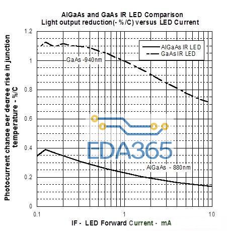
One of the important sources of AC error is noise, which is inherent in the semiconductor chip design and process. Because most sensor signals are amplified by high-gain blocks, the input referred noise is also amplified by that same gain. Noise comes in two forms: pink noise (also called 1/f or flicker noise), and white noise. Pink noise is more critical at lower frequencies (< 100Hz or so), and white noise generally determines the chip performance at higher signal bandwidths (Figure 1). Since most IAs deal with low-frequency signals, this article examines pink noise more closely.
Figure 1. Noise density in semiconductor devices.
In traditional low-noise analog-circuit design, bipolar transistors are often preferred for use in input-stage circuitry, especially if low levels of pink noise must be achieved. Pink noise originates as recombination effects at defect sites on the semiconductor surface and, therefore, CMOS device noise tends to have a larger magnitude and a higher corner frequency than does bipolar device noise. (The frequency at which the pink noise density equals the white noise density is defined as the noise corner frequency.)
Most sensors prefer high-impedance inputs, which forces the use of CMOS front-ends on IAs. This in turn would seem to make it necessary to accept the accompanying higher levels of low-frequency noise. Fortunately, zero-drift circuit-design techniques that continuously cancel out input offset voltages also tend to cancel the low-frequency input pink noise.
Cool New Architectures Are Really Hot: Three Op Amps vs. Indirect Current Feedback
A traditional IA uses three op amps to create an input buffer stage and an output stage (Figure 2). The input buffer stage provides all differential gain, unity common-mode gain, and a high-impedance input. The differential amplifier output stage then provides a unity differential gain with zero common-mode gain. This IA works quite well in many applications, but its simplicity hides two significant drawbacks: the usable input common-mode voltage range is limited, and its AC CMRR is limited.
Figure 2. A traditional three-op-amp IA.
IAs based on three-op-amp architectures suffer a restrictive transfer characteristic (Figure 3). Their architecture can allow the outputs of buffer amplifiers A1 and A2 to saturate into the power-supply rails during a certain combination of input common-mode and input differential voltage. In this condition, the IA no longer rejects input common-mode voltages.
Figure 3. Limited transfer characteristic at various common-mode voltages (at high gain, the "eye" compresses).
As a result, the data sheets for most three-op-amp IAs show a plot of the usable input common-mode voltage vs. output voltage. Because output voltage is simply a scaled version of the input differential voltage, the two axes of this plot could as well be labeled "input common-mode voltage" and "input differential voltage." The gray area within the hexagon depicts the "valid" zone of operation, within which the outputs of amplifiers A1 and A2 are not saturated into the power-supply rails.
Note that the Figure 3 graph has an important implication for single-supply applications. Common-mode voltages can easily approach the circuit ground, to which the gray zone does not extend. Certain applications (such as low-side current sensing) cannot use a traditional three-op-amp IA, because the input common-mode voltage equals the ground potential.
Three-op-amp IAs achieve high common-mode rejection at DC by matching on-chip resistors around the differential amplifier, but the feedback architecture of such IAs can substantially degrade the AC CMRR. To overcome this and other drawbacks, alternate IA architectures have been developed. The two-gM indirect current-feedback approach, for instance, has found considerable success (Figure 4).
Figure 4. Indirect current-feedback architecture for IAs.
The two-gM architecture consists of two matched transconductance amplifiers and a high-gain amplifier. Because the matched amplifiers have the same gM, they develop equal differential voltages at their inputs, and the output voltage is therefore determined by the resistor divider ratio Rf/Rg. The output common-mode voltage is set by voltage at the REF pin. Voltage-to-current conversion implemented by the input gM amplifier inherently rejects the input common-mode voltage, giving the amplifier a high DC and AC CMRR.
The indirect current-feedback IA architecture allows a full output-voltage swing, even when the input common-mode voltage equals the negative supply rail. Thus, it offers an expanded range of operation not obtainable with the three-op-amp IA architectures. Examples of this IA type that are available from Maxim include the MAX4460/MAX4461/MAX4462 and the MAX4208/MAX4209.
Offset-Cancellation Techniques: Catch the Drift?
As mentioned above, two important specifications for IAs are pink noise (also called 1/f or flicker noise), and VOS and its drift (vs. temperature and time). Because 1/f noise is a low-frequency phenomenon, many of the circuit techniques used to achieve "zero drift" and cancellation of input-offset voltage also remove 1/f noise. These techniques include sampling amplifiers, auto zeroing amplifiers, chopper amplifiers, chopper-stabilized amplifiers, and chopper-chopper-stabilized amplifiers (the MAX4208, for example). These architectures are described in multiple articles and patents (see References), and each offers a different combination of usable signal bandwidth, switching noise, and the resulting accuracy of input-offset cancellation.
For example, sampling techniques based on flying capacitors have been applied to IAs for the purpose of autocorrecting input offset voltages. However, because a sampled input is not truly a high-impedance structure, the resulting system-level accuracy can be compromised by a mismatch in source resistances, such as those found in certain unbalanced bridges.
Applications
This section describes two IA applications: a ratiometric bridge circuit and a low-side current-sense amplifier.
Bridge over Troubled Waters
A variation of the standard bridge-measurement system is the ratiometric bridge, which delivers similar high accuracy but at a lower cost. Cost is lower because the ratiometric bridge does not require a precision reference source for driving the bridge and ADC reference input. Instead, a "free" but relatively inaccurate and high-ppm/°C reference source such as the power-supply rail can be used to drive both the bridge and the ADC.
It is well known that even an op amp with rail-to-rail output has trouble maintaining full accuracy while driving its output to within a few hundred millivolts of either rail. For an amplifier with high dynamic range and unipolar-signal inputs, it is therefore necessary to bias the output above ground by 250mV or so. This bias voltage drives one end of a resistor chain and therefore should be driven by a buffer of low output impedance to avoid introducing unintentional gain errors. To minimize output errors, this unity-gain op-amp buffer should also have low DC offset and low drift.
An IA from Maxim (e.g., the MAX4208) integrates a precision, zero-drift op-amp buffer and a two-gM indirect current-feedback IA in a small µMAX® package. This buffer and a simple external resistor divider (Figure 5) can be used to create a stable bias reference voltage that is ratiometric with the ADC reference voltage. It can also drive one of the inputs of a differential input ADC. The internal chopper-chopper-stabilized architecture of the IA eliminates pink noise effects in both the op-amp buffer and the gM amplifiers of the main (forward) and feedback paths. The part also includes a shutdown mode that is useful for power-sensitive applications.
Figure 5. Driving a ratiometric bridge (MAX4208–MAX4209).
Make Perfect Current-Sense
The increasing need for active power management in today's portable electronic devices has led to a renewal of interest in current-sensing amplifiers. A ground-sensing IA can be used as a high-side current-sense amplifier in the core-voltage path of a memory module or microprocessor (Figure 6), or as a low-side current-sense amplifier in the return path of an H-bridge power electronic converter. The extremely high currents in these applications (sometimes approaching 90A) imply that the sense voltage must be extremely small to prevent excessive power loss in the sense resistor. Quite often, this sense resistor is simply the ESR of the power-supply inductor itself. To read these small sense voltages accurately, the VOS must be extremely small in comparison with smallest sense voltage (i.e., smallest load current) that is required to be amplified with accuracy.
Figure 6. Sensing high current in computer applications (MAX4208).
Core voltages in computer hardware can vary from 0.9V to 1.5V, and thus the small sense voltage must be measured in the presence of a common-mode voltage that is low and varying. An IA such as the MAX4208 with low VOS, high CMRR, and an architecture optimized for single-supply applications is, therefore, ideal for this purpose.
Conclusion
New applications are continually fueling the quest for ideal instrumentation amplifiers, as is evident from the multiple architectures available for tackling the challenges of VOS, drift of VOS, and 1/f noise. To fully leverage the benefits of chip technology, it is useful to understand the nuances of instrumentation amplifier design, and how that design relates to the needs of the application.
References
- Thomas Frederiksen, Intuitive IC Op Amps (National Semiconductor Technology Series, 1984).
- Horowitz, Paul, & Hill, Winfield, The Art of Electronics (Cambridge University Press, 1989).
- Graeme, Jerald, Optimizing Op Amp Performance (McGraw-Hill, 1997).
- Huijsing, Johan, Operational Amplifiers—Theory and Design (Kluwer Academic Publishers, 2001).
- Maxim Integrated Products, Inc., "Chopper chopper-stabilized operational amplifiers and methods," U.S. Patent #6734723 (May 11, 2004).
- Nolan, Eric, Moghimi, Reza, "Demystifying Auto-Zero Amplifiers," Analog Dialogue (Analog Devices, Inc., May 2000).
- Kugelstadt, Thomas, "Auto-zero amplifiers ease the design of high-precision circuits," TI Analog Applications Journal (2005).
µMAX is a registered trademark of Maxim Integrated Products, Inc.
Intel is a registered trademark of Intel Corporation.
Pentium is a registered trademark of Intel Corp.
『本文转载自网络,版权归原作者所有,如有侵权请联系删除』


 热门文章
更多
热门文章
更多

 ZigBee技术语音图像无线监控系统的设计与实现


 APP下载
APP下载 登录
登录


