×


单片机源程序如下:
/*
* Project name:
Seven Segment Display (The 'Hello World' example for the Seven Segment Display)
* Copyright:
(c) Mikroelektronika, 2011.
* Revision History:
20110929:
- initial release (FJ);
* Description:
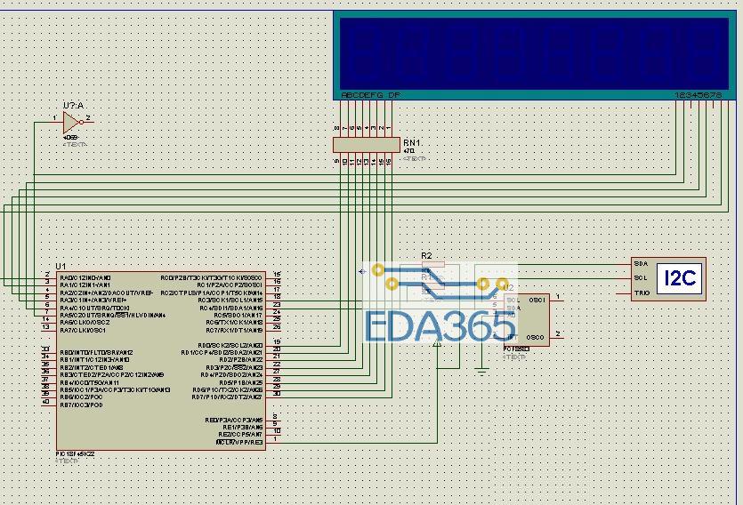
This code demonstrates how to display number on one 7-segment display
(common cathode). Display is connected to PORTD (RD0..RD7, segment A to
RD0, segment B to RD1, etc); common cathode is connected to the pin RA0 on
PORTA. Number is incremented every 1s.
* NOTES:
- Turn on Seven Segment Display switches SW4.1, SW4.2, SW4.3 and SW4.4. (board specific)
*/
#include "Display_Utils.h"
//unsigned short portd_index;
char seconds, minutes, hours, day, month, year; // Global date/time variables
char i;
// Software I2C connections
/*sbit Soft_I2C_Scl at RC3_bit;
sbit Soft_I2C_Sda at RC4_bit;
sbit Soft_I2C_Scl_Direction at TRISC3_bit;
sbit Soft_I2C_Sda_Direction at TRISC4_bit;
*/
// End Software I2C connections
//--------------------- Reads time and date information from RTC (PCF8583)
void Read_Time() {
I2C1_Start(); // Issue start signal
I2C1_Wr(0xA0); // Address PCF8583, see PCF8583 datasheet
I2C1_Wr(2); // Start from address 2
I2C1_Repeated_Start(); // issue I2C signal repeated start
//I2C1_Start(); // Issue repeated start signal
I2C1_Wr(0xA1); // Address PCF8583 for reading R/W=1
seconds = I2C1_Rd(1); // Read seconds byte
minutes = I2C1_Rd(1); // Read minutes byte
hours = I2C1_Rd(1); // Read hours byte
day = I2C1_Rd(1); // Read year/day byte
month = I2C1_Rd(0); // Read weekday/month byte
I2C1_Stop(); // Issue stop signal
}
//-------------------- Formats date and time
void Transform_Time() {
seconds = ((seconds & 0xF0) >> 4)*10 + (seconds & 0x0F); // Transform seconds
minutes = ((minutes & 0xF0) >> 4)*10 + (minutes & 0x0F); // Transform months
hours = ((hours & 0xF0) >> 4)*10 + (hours & 0x0F); // Transform hours
year = (day & 0xC0) >> 6; // Transform year
day = ((day & 0x30) >> 4)*10 + (day & 0x0F); // Transform day
month = ((month & 0x10) >> 4)*10 + (month & 0x0F); // Transform month
}
/*
void interrupt() {
LATD = 0; // Turn off all 7seg displays
LATD = mask(hours/10u); // bring appropriate value to PORTD
LATA = 0b011111; // turn on appropriate 7seg. display
Delay_ms(2);
LATD=0;
LATD = mask(hours%10u);
LATA = 0b101111;
Delay_ms(2);
LATD=0;
LATD = mask(minutes/10u);
LATA = 0b110111;
Delay_ms(2);
LATD=0;
LATD = mask(minutes%10u);
LATA = 0b111011;
Delay_ms(2);
LATD=0;
LATD = mask(seconds/10u);
LATA = 0b111101;
Delay_ms(2);
LATD=0;
LATD = mask(seconds%10u);
LATA = 0b111110;
Delay_ms(2);
LATD=0;
TMR0L = 0; // reset TIMER0 value
TMR0IF_bit = 0; // Clear TMR0IF
} */
void main() {
ANSELA = 0; // Configure PORTA pins as digital
ANSELD = 0; // Configure PORTD pins as digital
TRISA = 0; // Configure PORTA as output
LATA = 0; // Clear PORTA
TRISD = 0; // Configure PORTD as output
LATD = 0; // Clear PORTD
//T0CON = 0xC4; // Set TMR0 in 8bit mode, assign prescaler to TMR0
//TMR0L = 0; // clear TMROL
//GIE_bit = 1;
//TMR0IE_bit = 1;
I2C1_Init(100000); // initialize I2C communication
//Soft_I2C_Init(); // Initialize Soft I2C communication
do {
Read_Time(); // Read time from RTC(PCF8583)
Transform_Time(); // Format date and time
for (i=0;i<32;i++)
{
LATD = 0; // Turn off all 7seg displays
LATD = mask(hours/10u); // bring appropriate value to PORTD
LATA = 0b011111; // turn on appropriate 7seg. display
Delay_ms(20);
LATD=0;
LATD = mask(hours%10u);
LATA = 0b101111;
Delay_ms(20);
LATD=0;
LATD = mask(minutes/10u);
LATA = 0b110111;
Delay_ms(20);
LATD=0;
LATD = mask(minutes%10u);
LATA = 0b111011;
Delay_ms(20);
LATD=0;
LATD = mask(seconds/10u);
LATA = 0b111101;
Delay_ms(20);
LATD=0;
LATD = mask(seconds%10u);
LATA = 0b111110;
Delay_ms(20);
LATD=0;
}
//Delay_ms(4000); // one second delay
} while(1); // endless loop
}
『本文转载自网络,版权归原作者所有,如有侵权请联系删除』


 热门文章
更多
热门文章
更多

 8051单片机的函数发生器的设计


 APP下载
APP下载 登录
登录


