按键的硬件结构有一点一定要注意,要在GPIO段上拉电阻,否则GPIO设置成浮空输入后,会造成端口电平不稳定,中断效果不理想。
另外EXTI的映射关系可以看下图,是和管脚号对应的,比较好记
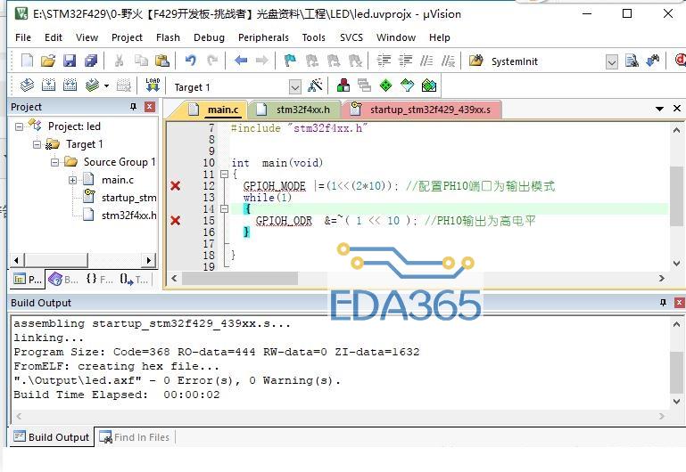
(1)Main
C语言: Codee#14817
/*++++++++++++++++++++++++++++++++++++++++++++++++++++++++++++++++++++++++++++++
+ 实验平台 : ST 官方三合一套件
+ 硬件 : STM32F103C8T6
+ 开发平台 : IAR For ARM 5.40
+ 仿真器 : J-Link
+ 日期 : 2010-11-4
+ 频率 :HSE = 8MHz ,主频 = 72MHz
++++++++++++++++++++++++++++++++++++++++++++++++++++++++++++++++++++++++++++++*/
#include "includes.h"
/*******************************************************************************
== Main 函数 ==
*******************************************************************************/
int main(void)
{
RCC_Configuration(); //配置系统时钟
NVIC_Configuration(); //配置 NVIC 和 Vector Table
SysTick_Config(); //配置SysTick的精确延时
GPIO_Configuration();
EXTI_Configuration();
LED1_HIGH ; LED2_HIGH ; LED3_HIGH ; LED4_HIGH ; // 初始化让灯全灭
while (1)
{
if( KEY_UP == 0 )
{ LED1_LOW ;}
if( KEY_DOWN == 0 )
{ LED2_LOW ;}
if( KEY_LEFT == 0 )
{ LED3_LOW ;}
if( KEY_RIGHT == 0 )
{ LED4_LOW ;}
}
}
(2)Unique_Device_ID.c
C语言: Codee#14816
#include "includes.h"
/*******************************************************************************
== 全局变量 ==
*******************************************************************************/
vu32 TimingDelay; // 精确延时在SysTick中断里用的计数变量
/*******************************************************************************
* Function Name : RCC_Configuration 配置时钟
* Description : Configures the different system clocks.
* Input : None
* Output : None
* Return : None
*******************************************************************************/
void RCC_Configuration(void)
{
ErrorStatus HSEStartUpStatus;
//将外设 RCC寄存器重设为缺省值
RCC_DeInit();
//设置外部高速晶振(HSE)
RCC_HSEConfig(RCC_HSE_ON);
//等待 HSE 起振
HSEStartUpStatus = RCC_WaitForHSEStartUp();
if(HSEStartUpStatus == SUCCESS)
{
//预取指缓存使能
FLASH_PrefetchBufferCmd(FLASH_PrefetchBuffer_Enable);
//设置代码延时值
//FLASH_Latency_2 2 延时周期
FLASH_SetLatency(FLASH_Latency_2);
//设置 AHB 时钟(HCLK)
//RCC_SYSCLK_Div1 AHB 时钟 = 系统时钟
RCC_HCLKConfig(RCC_SYSCLK_Div1);
//设置高速 AHB 时钟(PCLK2)
//RCC_HCLK_Div2 APB1 时钟 = HCLK / 2
RCC_PCLK2Config(RCC_HCLK_Div2);
//设置低速 AHB 时钟(PCLK1)
//RCC_HCLK_Div2 APB1 时钟 = HCLK / 2
RCC_PCLK1Config(RCC_HCLK_Div2);
// PLLCLK = 8MHz * 9 = 72 MHz
//设置 PLL 时钟源及倍频系数
RCC_PLLConfig(RCC_PLLSource_HSE_Div1, RCC_PLLMul_9);
//使能或者失能 PLL
RCC_PLLCmd(ENABLE);
//等待指定的 RCC 标志位设置成功 等待PLL初始化成功
while(RCC_GetFlagStatus(RCC_FLAG_PLLRDY) == RESET)
{
}
//设置系统时钟(SYSCLK) 设置PLL为系统时钟源
RCC_SYSCLKConfig(RCC_SYSCLKSource_PLLCLK);
//等待PLL成功用作于系统时钟的时钟源
// 0x00:HSI 作为系统时钟
// 0x04:HSE作为系统时钟
// 0x08:PLL作为系统时钟
while(RCC_GetSYSCLKSource() != 0x08)
{
}
}
//RCC_APB2PeriphClockCmd(RCC_APB2Periph_ALL, ENABLE);
//使能或者失能 APB2 外设时钟
RCC_APB2PeriphClockCmd(RCC_APB2Periph_GPIOA | RCC_APB2Periph_AFIO, ENABLE);
RCC_APB2PeriphClockCmd(RCC_APB2Periph_GPIOB, ENABLE);
RCC_APB2PeriphClockCmd(RCC_APB2Periph_GPIOC, ENABLE);
RCC_APB2PeriphClockCmd(RCC_APB2Periph_GPIOD, ENABLE);
}
/*******************************************************************************
* Function Name : NVIC_Configuration 配置中断优先级
* Description : Configures NVIC and Vector Table base location.
* Input : None
* Output : None
* Return : None
*******************************************************************************/
void NVIC_Configuration(void)
{
NVIC_InitTypeDef NVIC_InitStructure_EXTI_LINE7;
#ifdef VECT_TAB_RAM
/* Set the Vector Table base location at 0x20000000 */
NVIC_SetVectorTable(NVIC_VectTab_RAM, 0x0);
#else /* VECT_TAB_FLASH */
/* Set the Vector Table base location at 0x08000000 */
NVIC_SetVectorTable(NVIC_VectTab_FLASH, 0x0);
#endif
//===== NVIC_EXTI_PB7 ===================================================
/* Configure the NVIC Preemption Priority Bits */
NVIC_PriorityGroupConfig(NVIC_PriorityGroup_0);
/* Enable the EXTI PB7 Interrupt */
NVIC_InitStructure_EXTI_LINE7.NVIC_IRQChannel = EXTI9_5_IRQChannel; // 配置使能指定的IRQ(Interrupt ReQuest中断请求)通道
NVIC_InitStructure_EXTI_LINE7.NVIC_IRQChannelPreemptionPriority = 0; // 配置IRQ的 组 优先级
NVIC_InitStructure_EXTI_LINE7.NVIC_IRQChannelSubPriority = 0; // 配置IRQ的 从 优先级
NVIC_InitStructure_EXTI_LINE7.NVIC_IRQChannelCmd = ENABLE; // 配置IRQ 使能
NVIC_Init(&NVIC_InitStructure_EXTI_LINE7); // 初始化 UART1_IRQ
}
/*******************************************************************************
* Function Name : GPIO_Configuration 配置管教
* Description : Configures the different GPIO ports.
* Input : None
* Output : None
* Return : None
*******************************************************************************/
void GPIO_Configuration(void)
{
GPIO_InitTypeDef GPIO_InitStructure_LED_PORTB;
GPIO_InitTypeDef GPIO_InitStructure_KEY_PORTA;
GPIO_InitTypeDef GPIO_InitStructure_KEY_PORTB;
GPIO_InitTypeDef GPIO_InitStructure_KEY_PORTC;
//==== LED =======================================================
GPIO_InitStructure_LED_PORTB.GPIO_Pin = GPIO_Pin_12 | GPIO_Pin_13 | GPIO_Pin_14 | GPIO_Pin_15 ;
GPIO_InitStructure_LED_PORTB.GPIO_Speed = GPIO_Speed_50MHz;
GPIO_InitStructure_LED_PORTB.GPIO_Mode = GPIO_Mode_Out_PP; //推挽输出
GPIO_Init(GPIOB, &GPIO_InitStructure_LED_PORTB);
//==== KEY =======================================================
GPIO_InitStructure_KEY_PORTA.GPIO_Pin = GPIO_Pin_0 ;
GPIO_InitStructure_KEY_PORTA.GPIO_Speed = GPIO_Speed_50MHz;
GPIO_InitStructure_KEY_PORTA.GPIO_Mode = GPIO_Mode_IPU ; //上拉输入
GPIO_Init(GPIOA, &GPIO_InitStructure_KEY_PORTA);
GPIO_InitStructure_KEY_PORTB.GPIO_Pin = GPIO_Pin_7 ;
GPIO_InitStructure_KEY_PORTB.GPIO_Speed = GPIO_Speed_50MHz;
GPIO_InitStructure_KEY_PORTB.GPIO_Mode = GPIO_Mode_IN_FLOATING; //浮空输入 ,外部中断按键
GPIO_Init(GPIOB, &GPIO_InitStructure_KEY_PORTB);
GPIO_InitStructure_KEY_PORTC.GPIO_Pin = GPIO_Pin_13 | GPIO_Pin_14 | GPIO_Pin_15 ;
GPIO_InitStructure_KEY_PORTC.GPIO_Speed = GPIO_Speed_50MHz;
GPIO_InitStructure_KEY_PORTC.GPIO_Mode = GPIO_Mode_IPU; //上拉输入
GPIO_Init(GPIOC, &GPIO_InitStructure_KEY_PORTC);
}
/*******************************************************************************
* Function Name : EXTI_Configuration 配置外部中断管教
* Description : Configures the EXTI
* Input : None
* Output : None
* Return : None
*******************************************************************************/
void EXTI_Configuration(void)
{
EXTI_InitTypeDef EXTI_InitStructure_EXTI_LINE7;
/* Connect EXTI Line7 to PB7 */
GPIO_EXTILineConfig(GPIO_PortSourceGPIOB, GPIO_PinSource7); // 配置 管脚PB7用作外部中断线路
/* Configure EXTI Line7 to generate an interrupt on falling edge */
EXTI_InitStructure_EXTI_LINE7.EXTI_Line = EXTI_Line7; //配置 使能或失能的外部线路
EXTI_InitStructure_EXTI_LINE7.EXTI_Mode = EXTI_Mode_Interrupt; //配置 EXTI线路为中断请求 (或者是事件请求)
EXTI_InitStructure_EXTI_LINE7.EXTI_Trigger = EXTI_Trigger_Falling; //配置 使能线路的触发边沿 -- 下降沿触发中断
EXTI_InitStructure_EXTI_LINE7.EXTI_LineCmd = ENABLE; //配置 状态为使能
EXTI_Init(&EXTI_InitStructure_EXTI_LINE7); // 初始化外部中断线路7
/* Generate software interrupt: simulate a falling edge applied on EXTI line 7 */
EXTI_GenerateSWInterrupt(EXTI_Line7); //线路7产生一个软件中断
}
/*******************************************************************************
* Function Name : SysTick_Config SysTick设置
* Description : Configures SysTick
* Input : None
* Output : None
* Return : None
*******************************************************************************/
void SysTick_Config(void)
{
/* Disable SysTick Counter */
SysTick_CounterCmd(SysTick_Counter_Disable);
/* Disable the SysTick Interrupt */
SysTick_ITConfig(DISABLE);
/* Configure HCLK clock as SysTick clock source */
SysTick_CLKSourceConfig(SysTick_CLKSource_HCLK_Div8);
/* SysTick interrupt each 1000 Hz with HCLK equal to 72MHz */
SysTick_SetReload(9000);
/* Enable the SysTick Interrupt */
SysTick_ITConfig(ENABLE);
}
/*******************************************************************************
* Function Name : 精确延时函数
*******************************************************************************/
void Delay_Ms(u32 nTime)
{
/* Enable the SysTick Counter */
SysTick_CounterCmd(SysTick_Counter_Enable);
TimingDelay = nTime;
while(TimingDelay != 0);
/* Disable SysTick Counter */
SysTick_CounterCmd(SysTick_Counter_Disable);
/* Clear SysTick Counter */
SysTick_CounterCmd(SysTick_Counter_Clear);
}
(4)stm32f10x_it.c
C语言: Codee#14818
/* Includes ------------------------------------------------------------------*/
#include "includes.h"
//#include "stm32f10x_it.h"
// ... ...
/*******************************************************************************
* Function Name : EXTI9_5_IRQHandler
* Description : This function handles External lines 9 to 5 interrupt request.
* Input : None
* Output : None
* Return : None
*******************************************************************************/
// LINE : 407
void EXTI9_5_IRQHandler(void)
{
if(EXTI_GetITStatus(EXTI_Line7) == SET) // 读取中断状态
{
LED1_HIGH ; LED2_HIGH ; LED3_HIGH ; LED4_HIGH ; // 灯全灭
EXTI_ClearITPendingBit(EXTI_Line7); // 清除标志位
}
}
// ... ...
『本文转载自网络,版权归原作者所有,如有侵权请联系删除』


 热门文章
更多
热门文章
更多

 C51 特殊功能寄存器SFR的名称和地址


 APP下载
APP下载 登录
登录


