
GPIO_Init函数是IO引脚的初始化函数,进行个个引脚的初始化配置,主要接受两个参数,一个是配置引脚组(GPIO_TypeDef* GPIOx),一个是配置的参数( GPIO_InitTypeDef* GPIO_InitStruct),具体如下
void GPIO_Init(GPIO_TypeDef* GPIOx, GPIO_InitTypeDef* GPIO_InitStruct)
/*其中第一个参数为那组引脚,每组拥有16个引脚,每组都具有不同的寄存器配置地址,第二个参数是一个数据结构,也就是将基本配置信息放在这个数据结构里面,再将这个结构传入函数进行配置*/
//其中数据机构可以表示为如下
typedef struct
{
uint16_t GPIO_Pin; //引脚号
GPIOSpeed_TypeDef GPIO_Speed; //配置速度
GPIOMode_TypeDef GPIO_Mode; //工作模式
}GPIO_InitTypeDef;
//其中配置模式和工作模式为GPIOSpeed_TypeDef和GPIOMode_TypeDef的枚举变量
为了方面的解析这个函数我们需要把几个常量的定义罗列一下
//首先是引脚定义
#define GPIO_Pin_0 ((uint16_t)0x0001) /* Pin 0 selected */
#define GPIO_Pin_1 ((uint16_t)0x0002) /* Pin 1 selected */
#define GPIO_Pin_2 ((uint16_t)0x0004) /* Pin 2 selected */
#define GPIO_Pin_3 ((uint16_t)0x0008) /* Pin 3 selected */
#define GPIO_Pin_4 ((uint16_t)0x0010) /* Pin 4 selected */
#define GPIO_Pin_5 ((uint16_t)0x0020) /* Pin 5 selected */
#define GPIO_Pin_6 ((uint16_t)0x0040) /* Pin 6 selected */
#define GPIO_Pin_7 ((uint16_t)0x0080) /* Pin 7 selected */
#define GPIO_Pin_8 ((uint16_t)0x0100) /* Pin 8 selected */
#define GPIO_Pin_9 ((uint16_t)0x0200) /* Pin 9 selected */
#define GPIO_Pin_10 ((uint16_t)0x0400) /* Pin 10 selected */
#define GPIO_Pin_11 ((uint16_t)0x0800) /* Pin 11 selected */
#define GPIO_Pin_12 ((uint16_t)0x1000) /* Pin 12 selected */
#define GPIO_Pin_13 ((uint16_t)0x2000) /* Pin 13 selected */
#define GPIO_Pin_14 ((uint16_t)0x4000) /* Pin 14 selected */
#define GPIO_Pin_15 ((uint16_t)0x8000) /* Pin 15 selected */
#define GPIO_Pin_All ((uint16_t)0xFFFF) /* All pins selected */
//其次是模式定义
typedef enum
{ GPIO_Mode_AIN = 0x0, //模拟输入
GPIO_Mode_IN_FLOATING = 0x04, //浮空输入模式, 默认
GPIO_Mode_IPD = 0x28, //上拉/下拉输入模式
GPIO_Mode_IPU = 0x48, //保留
GPIO_Mode_Out_OD = 0x14, //通用开漏输出
GPIO_Mode_Out_PP = 0x10, //通用推挽输出
GPIO_Mode_AF_OD = 0x1C, //复用(开漏)输出
GPIO_Mode_AF_PP = 0x18 //复用(推挽)输出
}GPIOMode_TypeDef;
//最后是速度定义
typedef enum
{
GPIO_Speed_10MHz = 1,
GPIO_Speed_2MHz,
GPIO_Speed_50MHz
}GPIOSpeed_TypeDef;
其中引脚定义很容以看出引脚0则16位的第0位 置1 ,引脚为2则第2位置1,一次类推,所以如果要定义多个引脚只需要使用或逻辑运算(|)
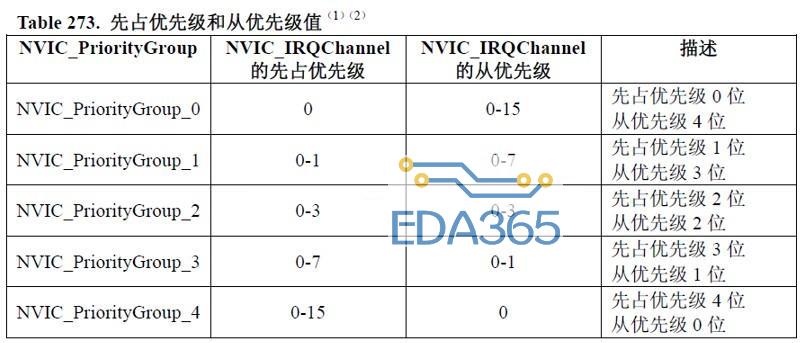
其次模式定义也有他的规律,参考《stmf10xxx参考手册》可以得出知道存储的高低配置寄存器中每4位表达一个模式+速度,其中模式占高2位,速度占低2位,16个引脚就拥有4*16=64位来存储,所以这样定义就有它的道理,原因就是模式占高位例如10表示上拉/下拉输出模式,则在4位中占高2位,就应该是1000,低2位先用00表示,这样的话上拉/下拉输出模式就可以表示为1000=0x8,或者用0x28的第四位表示也可以,其它也是一样,就是里面的第五位1表示输出模式,0表示输入模式。
速度就直接用1,2,3来表示
具体的函数分析如下
void GPIO_Init(GPIO_TypeDef* GPIOx, GPIO_InitTypeDef* GPIO_InitStruct)
{
/*初始化各个变量*/
uint32_t currentmode = 0x00, currentpin = 0x00, pinpos = 0x00, pos = 0x00;
uint32_t tmpreg = 0x00, pinmask = 0x00;
//currentmode 用于存放临时的LCIR
//currentpin 用于存放配置的引脚位
//pinpos 用于存放当前操作的引脚号
//pos 存放当前操作的引脚位
//tmreg 当前的CIR
//pinmask
//判断参数
assert_param(IS_GPIO_ALL_PERIPH(GPIOx));
assert_param(IS_GPIO_MODE(GPIO_InitStruct->GPIO_Mode));
assert_param(IS_GPIO_PIN(GPIO_InitStruct->GPIO_Pin));
//取出配置信息里面的模式信息并且取它的低4位
currentmode = ((uint32_t)GPIO_InitStruct->GPIO_Mode) & ((uint32_t)0x0F);
if ((((uint32_t)GPIO_OInitStruct->GPIO_Mode) & ((uint32_t)0x10)) != 0x00) //输出模式
{
//判断参数
assert_param(IS_GPIO_SPEED(GPIO_InitStruct->GPIO_Speed));
//将速度信息放入currentmode低二位
currentmode |= (uint32_t)GPIO_InitStruct->GPIO_Speed;
}
if (((uint32_t)GPIO_InitStruct->GPIO_Pin & ((uint32_t)0x00FF)) != 0x00) //引脚有定义
{
//当前的CRL保存
tmpreg = GPIOx->CRL;
//循环低八位引脚
for (pinpos = 0x00; pinpos
{
//当前是那个引脚,那个位置1
pos = ((uint32_t)0x01) <
//读取引脚信息里面的当前引脚
currentpin = (GPIO_InitStruct->GPIO_Pin) & pos;
if (currentpin == pos) //如果当前引脚在配置信息里存在
{
pos = pinpos <
pinmask = ((uint32_t)0x0F) <
tmpreg &= ~pinmask; //当前应该操作的CRL位清0
tmpreg |= (currentmode <
if (GPIO_InitStruct->GPIO_Mode == GPIO_Mode_IPD) // 端口置为高电平
{
GPIOx->BRR = (((uint32_t)0x01) <
}
else
{
if (GPIO_InitStruct->GPIO_Mode == GPIO_Mode_IPU) // 端口清0
{
GPIOx->BSRR = (((uint32_t)0x01) <
}
}
}
}
GPIOx->CRL = tmpreg;
}
最后就是把配置好的CRL传入CRL寄存器。设置完毕
『本文转载自网络,版权归原作者所有,如有侵权请联系删除』


 热门文章
更多
热门文章
更多

--处理器的状态,模式以及概括了解内部寄存器") 快速学Arm(9)--处理器的状态,模式以及概括了解内部寄存器
快速学Arm(9)--处理器的状态,模式以及概括了解内部寄存器


 APP下载
APP下载 登录
登录


