APP下载
APP下载 登录
登录


Comprising a standard Force-Sense lab power supply, an additional power supply for the ICs, and a separate control voltage, this adjustable current source provides a 1-to-1 ratio of control voltage to load current (1A/V).
A similar version of this article appeared in the October 16, 2008 issue of EDN magazine.
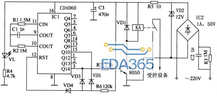
When electronic testing requires an adjustable current source, you must often build that piece of test equipment in the lab. You can easily make such a current source from a standard Force-Sense lab power supply (Figure 1). The circuit requires an additional power supply for the integrated circuits, and a separate control voltage.
Figure 1. Adding these components to a standard Force-Sense lab supply makes a simple voltage-controlled current source. As configured, the circuit produces a control ratio of 1:1 amperes per volt.
The feedback signal to the Force-Sense supply is derived from a high-side current monitor (MAX4172). In the configuration shown, the circuit offers a 1-to-1 ratio of control voltage to load current (1A/V). Load current as a function of load resistance is shown in Figure 2.
Figure 2. Load current vs. load resistance for the Figure 1 circuit.
To change the voltage/current ratio, simply change RSHUNT: a lower value of RSHUNT gives higher current, and vice-versa. Output current is limited by the maximum allowed voltage (150mV) between the RS+ and RS- terminals, the maximum RS+ voltage (32V), and of course, the maximum current capability of the Force-Sense supply.
Because voltage and current meters built into the Force-Sense supply will display inaccurate values while this circuit is operating, you should use external meters to monitor the load voltage and load current. Also, be aware that if the load is removed (IOUT = 0), the open-circuit voltage of the Force-Sense supply goes to the maximum value it can generate.
×


 热门文章
热门文章