×


例子为单片机的“Hello World”级的流水灯实验——虽然只有一个,其中并不是将完整的代码给出,只是给出关键部分来说明“如何调用ST公司的的库来完成对硬件的控制,以及对库文件代码进行跟踪和分析至寄存器级”。所以从第一段代码往下看就可以了,要用到的函数和变量大部分会说明,至于寄存器级的,那就只能翻手册了。
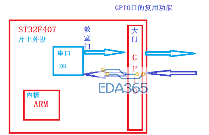
GPIO(General Purpose Input/Output) - 通用输入/输出
main.c :此函数为主函数,控制LED,亮1s,灭1s
int main(void)
{
//LED初始化
LED_Configuration();
while(1)
{
GPIO_SetBits(GPIOB,GPIO_Pin_5); //置为1
Systick_DelayMs(1000); //延时1s,自己实现的,暂不说明
GPIO_ResetBits(GPIOB,GPIO_Pin_5); //置为0
Systick_DelayMs(1000); //延时1s
}
}
stm32f10x_gpio.c GPIO_SetBits和GPIO_ResetBits
/**
* @brief Sets the selected data port bits.
* @param GPIOx: where x can be (A..G) to select the GPIO peripheral.
* @param GPIO_Pin: specifies the port bits to be written.
* This parameter can be any combination of GPIO_Pin_x where x can be (0..15).
* @retval None
*/
void GPIO_SetBits(GPIO_TypeDef* GPIOx, uint16_t GPIO_Pin)
{
/* Check the parameters */
assert_param(IS_GPIO_ALL_PERIPH(GPIOx));
assert_param(IS_GPIO_PIN(GPIO_Pin));
GPIOx->BSRR = GPIO_Pin;
}
/**
* @brief Clears the selected data port bits.
* @param GPIOx: where x can be (A..G) to select the GPIO peripheral.
* @param GPIO_Pin: specifies the port bits to be written.
* This parameter can be any combination of GPIO_Pin_x where x can be (0..15).
* @retval None
*/
void GPIO_ResetBits(GPIO_TypeDef* GPIOx, uint16_t GPIO_Pin)
{
/* Check the parameters */
assert_param(IS_GPIO_ALL_PERIPH(GPIOx));
assert_param(IS_GPIO_PIN(GPIO_Pin));
GPIOx->BRR = GPIO_Pin;
}
led.c 需要用到以下库文件:stm32f10x_rcc.c,stm32f10x_gpio.c-->STM32的I/O口初始化函数
void LED_Configuration(void)
{
/*设置PB.5为输出模式,用于LED*/
//定义一个GPIO数据结构,存放设置的参数
GPIO_InitTypeDef GPIO_InitStructure;
//要使用一个I/O口时,需要先打开相应I/O口所在口的时钟,如使能PB端口时钟
RCC_APB2PeriphClockCmd(RCC_APB2Periph_GPIOB, ENABLE);
//先设置要配置的引脚,LED0-->PB.5 端口配置
GPIO_InitStructure.GPIO_Pin = GPIO_Pin_5;
//配置为推挽输出模式
GPIO_InitStructure.GPIO_Mode = GPIO_Mode_Out_PP;
//配置I/O口速度为50MHz
GPIO_InitStructure.GPIO_Speed = GPIO_Speed_50MHz;
//根据设定参数初始化GPIOB
GPIO_Init(GPIOB, &GPIO_InitStructure);
}
下面为LED_Configuration中涉及到的结构体变量和一些其他变量的出处:
stm32f10x_gpio.h
/**
* @brief GPIO Init structure definition
*/
typedef struct
{
uint16_t GPIO_Pin; /*!< Specifies the GPIO pins to be configured.
This parameter can be any value of @ref GPIO_pins_define */
GPIOSpeed_TypeDef GPIO_Speed; /*!< Specifies the speed for the selected pins.
This parameter can be a value of @ref GPIOSpeed_TypeDef */
GPIOMode_TypeDef GPIO_Mode; /*!< Specifies the operating mode for the selected pins.
This parameter can be a value of @ref GPIOMode_TypeDef */
} GPIO_InitTypeDef;
stm32f10x_gpio.h :每个GPIO口有0x10个。
/** @defgroup GPIO_pins_define
* @{
*/
#define GPIO_Pin_0 ((uint16_t)0x0001) /*!< Pin 0 selected */
#define GPIO_Pin_1 ((uint16_t)0x0002) /*!< Pin 1 selected */
#define GPIO_Pin_2 ((uint16_t)0x0004) /*!< Pin 2 selected */
#define GPIO_Pin_3 ((uint16_t)0x0008) /*!< Pin 3 selected */
#define GPIO_Pin_4 ((uint16_t)0x0010) /*!< Pin 4 selected */
#define GPIO_Pin_5 ((uint16_t)0x0020) /*!< Pin 5 selected */
#define GPIO_Pin_6 ((uint16_t)0x0040) /*!< Pin 6 selected */
#define GPIO_Pin_7 ((uint16_t)0x0080) /*!< Pin 7 selected */
#define GPIO_Pin_8 ((uint16_t)0x0100) /*!< Pin 8 selected */
#define GPIO_Pin_9 ((uint16_t)0x0200) /*!< Pin 9 selected */
#define GPIO_Pin_10 ((uint16_t)0x0400) /*!< Pin 10 selected */
#define GPIO_Pin_11 ((uint16_t)0x0800) /*!< Pin 11 selected */
#define GPIO_Pin_12 ((uint16_t)0x1000) /*!< Pin 12 selected */
#define GPIO_Pin_13 ((uint16_t)0x2000) /*!< Pin 13 selected */
#define GPIO_Pin_14 ((uint16_t)0x4000) /*!< Pin 14 selected */
#define GPIO_Pin_15 ((uint16_t)0x8000) /*!< Pin 15 selected */
#define GPIO_Pin_All ((uint16_t)0xFFFF) /*!< All pins selected */
stm32f10x_gpio.h : GPIO的模式,比51多多了
/**
* @brief Configuration Mode enumeration
*/
typedef enum
{
GPIO_Mode_AIN = 0x0, /* 模拟输入模式 */
GPIO_Mode_IN_FLOATING = 0x04, /* 浮空输入模式 */
GPIO_Mode_IPD = 0x28, /* 下拉输入模式 */
GPIO_Mode_IPU = 0x48, /* 上拉输入模式 */
GPIO_Mode_Out_OD = 0x14, /* 通用推挽输出模式 */
GPIO_Mode_Out_PP = 0x10, /* 通用开漏输出模式 */
GPIO_Mode_AF_OD = 0x1C, /* 复用功能推挽输出模式 */
GPIO_Mode_AF_PP = 0x18 /* 复用功能开漏输出模式 */
} GPIOMode_TypeDef;
具体区别翻手册,也没记那么清楚~
stm32f10x_gpio.h : 赋予GPIO的运行频率
/**
* @brief Output Maximum frequency selection
*/
typedef enum
{
GPIO_Speed_10MHz = 1,
GPIO_Speed_2MHz,
GPIO_Speed_50MHz
} GPIOSpeed_TypeDef;
枚举变量:GPIO_Speed_10MHz =1;GPIO_Speed_2MHz =2;GPIO_Speed_50MHz =3,速度写着呢,选一个就ok了~
stm32f10x.h
#define PERIPH_BASE ((uint32_t)0x40000000) /*!< Peripheral base address in the alias region */
#define APB2PERIPH_BASE (PERIPH_BASE + 0x10000)
#define GPIOA_BASE (APB2PERIPH_BASE + 0x0800)
#define GPIOB_BASE (APB2PERIPH_BASE + 0x0C00)
#define GPIOC_BASE (APB2PERIPH_BASE + 0x1000)
#define GPIOD_BASE (APB2PERIPH_BASE + 0x1400)
#define GPIOE_BASE (APB2PERIPH_BASE + 0x1800)
#define GPIOF_BASE (APB2PERIPH_BASE + 0x1C00)
#define GPIOG_BASE (APB2PERIPH_BASE + 0x2000)
#define GPIOA ((GPIO_TypeDef *) GPIOA_BASE)
#define GPIOB ((GPIO_TypeDef *) GPIOB_BASE)
#define GPIOC ((GPIO_TypeDef *) GPIOC_BASE)
#define GPIOD ((GPIO_TypeDef *) GPIOD_BASE)
#define GPIOE ((GPIO_TypeDef *) GPIOE_BASE)
#define GPIOF ((GPIO_TypeDef *) GPIOF_BASE)
#define GPIOG ((GPIO_TypeDef *) GPIOG_BASE)
GPIOA=GPIOA_BASE=0x40000000+0x10000+0x800
通过查询STM32微控制器开发手册可以得知,STM32的外设起始基地址为0x40000000,而APB2总线设备起始地址相对于外设基地址的偏移量为0x10000,GPIOA设备相对于APB2总线设备起始地址偏移量为0x800。
注意:以上只是很小的一部分定义,stm32f10x.h文件的代码行数有8000多行。
下面为LED_Configuration中再配置完参数之后,将结构体中的参数写入到寄存器中的GPIO_Init初始化函数:
stm32f10x_gpio.c
/**
* @brief Initializes the GPIOx peripheral according to the specified
* parameters in the GPIO_InitStruct.
* @param GPIOx: where x can be (A..G) to select the GPIO peripheral.
* @param GPIO_InitStruct: pointer to a GPIO_InitTypeDef structure that
* contains the configuration information for the specified GPIO peripheral.
* @retval None
*/
void GPIO_Init(GPIO_TypeDef *GPIOx, GPIO_InitTypeDef *GPIO_InitStruct)
{
uint32_t currentmode = 0x00, currentpin = 0x00, pinpos = 0x00, pos = 0x00;
uint32_t tmpreg = 0x00, pinmask = 0x00;
/* Check the parameters */
//用断言来检查参数是否正确
assert_param(IS_GPIO_ALL_PERIPH(GPIOx));
assert_param(IS_GPIO_MODE(GPIO_InitStruct->GPIO_Mode));
assert_param(IS_GPIO_PIN(GPIO_InitStruct->GPIO_Pin));
/*---------------------------- GPIO Mode Configuration -----------------------*/
//将工作模式暂存至currentmode变量中
currentmode = ((uint32_t)GPIO_InitStruct->GPIO_Mode) & ((uint32_t)0x0F);
//如果欲设置为任意一种输出模式,则再检查“翻转速率”参数是否正确
if((((uint32_t)GPIO_InitStruct->GPIO_Mode) & ((uint32_t)0x10)) != 0x00)
{
/* Check the parameters */
assert_param(IS_GPIO_SPEED(GPIO_InitStruct->GPIO_Speed));
/* Output mode */
currentmode |= (uint32_t)GPIO_InitStruct->GPIO_Speed;
}
/*---------------------------- GPIO CRL Configuration ------------------------*/
/* Configure the eight low port pins */
//设置低8位引脚(即pin0~pin7)
if(((uint32_t)GPIO_InitStruct->GPIO_Pin & ((uint32_t)0x00FF)) != 0x00)
{
//独处当前配置字
tmpreg = GPIOx->CRL;
for(pinpos = 0x00; pinpos < 0x08; pinpos++)
{
pos = ((uint32_t)0x01) << pinpos;
/* Get the port pins position */
//获取将要配置的引脚号
currentpin = (GPIO_InitStruct->GPIO_Pin) & pos;
if(currentpin == pos)
{
//先清除对应引脚的配置字
pos = pinpos << 2;
/* Clear the corresponding low control register bits */
pinmask = ((uint32_t)0x0F) << pos;
tmpreg &= ~pinmask;
/* Write the mode configuration in the corresponding bits */
//写入新的配置字
tmpreg |= (currentmode << pos);
/* Reset the corresponding ODR bit */
//若欲配置为上拉/下拉输入,则需要配置BRR和BSRR寄存器
if(GPIO_InitStruct->GPIO_Mode == GPIO_Mode_IPD)
{
GPIOx->BRR = (((uint32_t)0x01) << pinpos);
}
else
{
/* Set the corresponding ODR bit */
if(GPIO_InitStruct->GPIO_Mode == GPIO_Mode_IPU)
{
GPIOx->BSRR = (((uint32_t)0x01) << pinpos);
}
}
}
}
//写入低8位引脚配置字
GPIOx->CRL = tmpreg;
}
/*---------------------------- GPIO CRH Configuration ------------------------*/
/* Configure the eight high port pins */
//设置高8位引脚(即pin8~pin15),流程和低8位引脚一致
if(GPIO_InitStruct->GPIO_Pin > 0x00FF)
{
tmpreg = GPIOx->CRH;
for(pinpos = 0x00; pinpos < 0x08; pinpos++)
{
pos = (((uint32_t)0x01) << (pinpos + 0x08));
/* Get the port pins position */
currentpin = ((GPIO_InitStruct->GPIO_Pin) & pos);
if(currentpin == pos)
{
pos = pinpos << 2;
/* Clear the corresponding high control register bits */
pinmask = ((uint32_t)0x0F) << pos;
tmpreg &= ~pinmask;
/* Write the mode configuration in the corresponding bits */
tmpreg |= (currentmode << pos);
/* Reset the corresponding ODR bit */
if(GPIO_InitStruct->GPIO_Mode == GPIO_Mode_IPD)
{
GPIOx->BRR = (((uint32_t)0x01) << (pinpos + 0x08));
}
/* Set the corresponding ODR bit */
if(GPIO_InitStruct->GPIO_Mode == GPIO_Mode_IPU)
{
GPIOx->BSRR = (((uint32_t)0x01) << (pinpos + 0x08));
}
}
}
GPIOx->CRH = tmpreg;
}
}
这段程序的流程:首先检查由结构体变量GPIO_InitStructure所传入的参数是否正确,然后对GPIO寄存器进行“读出->修改->写入”操作,完成对GPIO设备的配置工作。
总结起来就是:固件库首先将各个设备所有的寄存器的配置字进行预先定义在stm32f10x.h文件中,然后封装在结构或枚举变量中(存在相对应的stm32f10x_xxx.h,其中xxx代表gpio,spi,exti等外设模块),待用户调用对应的固件库函数时,会根据用户传入的参数从这些封装好的结构体或枚举变量中取出对应的配置字,最后写入寄存器中,完成对底层寄存器的配置。
stdint.h 一些具有可移植性的变量重定义
/*
* 'signed' is redundant below, except for 'signed char' and if
* the typedef is used to declare a bitfield.
* '__int64' is used instead of 'long long' so that this header
* can be used in --strict mode.
*/
/* 7.18.1.1 */
/* exact-width signed integer types */
typedef signed char int8_t;
typedef signed short int int16_t;
typedef signed int int32_t;
typedef signed __int64 int64_t;
/* exact-width unsigned integer types */
typedef unsigned char uint8_t;
typedef unsigned short int uint16_t;
typedef unsigned int uint32_t;
typedef unsigned __int64 uint64_t;
/* 7.18.1.2 */
/* smallest type of at least n bits */
/* minimum-width signed integer types */
typedef signed char int_least8_t;
typedef signed short int int_least16_t;
typedef signed int int_least32_t;
typedef signed __int64 int_least64_t;
/* minimum-width unsigned integer types */
typedef unsigned char uint_least8_t;
typedef unsigned short int uint_least16_t;
typedef unsigned int uint_least32_t;
typedef unsigned __int64 uint_least64_t;
/* 7.18.1.3 */
/* fastest minimum-width signed integer types */
typedef signed int int_fast8_t;
typedef signed int int_fast16_t;
typedef signed int int_fast32_t;
typedef signed __int64 int_fast64_t;
/* fastest minimum-width unsigned integer types */
typedef unsigned int uint_fast8_t;
typedef unsigned int uint_fast16_t;
typedef unsigned int uint_fast32_t;
typedef unsigned __int64 uint_fast64_t;
/* 7.18.1.4 integer types capable of holding object pointers */
typedef signed int intptr_t;
typedef unsigned int uintptr_t;
/* 7.18.1.5 greatest-width integer types */
typedef signed __int64 intmax_t;
typedef unsigned __int64 uintmax_t;
『本文转载自网络,版权归原作者所有,如有侵权请联系删除』


 热门文章
更多
热门文章
更多

 如何升级STM32单片机的代码


 APP下载
APP下载 登录
登录


