×


摘要:本文针对由FPGA构成的高速数据采集系统数据处理能力弱的问题,提出FPGA与单片机实现数据串行通信的解决方案。在通信过程中完全遵守RS232协议,具有较强的通用性和推广价值。
现场可编程逻辑器件(FPGA)在高速采集系统中的应用越来越广,由于FPGA对采集到的数据的处理能力比较差,故需要将其采集到的数据送到其他CPU系统来实现数据的处理功能,这就使FPGA系统与其他CPU系统之间的数据通信提到日程上,得到人们的急切关注。本文介绍利用VHDL语言实现 FPGA与单片机的串口异步通信电路。
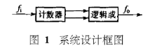
整个设计采用模块化的设计思想,可分为四个模块:FPGA数据发送模块,FPGA波特率发生控制模块,FPGA总体接口模块以及单片机数据接收模块。本文着重对FPGA数据发送模块实现进行说明。
根据RS232 异步串行通信来的帧格式,在FPGA发送模块中采用的每一帧格式为:1位开始位+8位数据位+1位奇校验位+1位停止位,波特率为2400。本系统设计的是将一个16位的数据封装成高位帧和低位帧两个帧进行发送,先发送低位帧,再发送高位帧,在传输数据时,加上文件头和数据长度,文件头用555555来表示,只有单片机收到555555时,才将下面传输的数据长度和数据位进行接收,并进行奇校验位的检验,正确就对收到的数据进行存储处理功能,数据长度可以根据需要任意改变。由设置的波特率可以算出分频系数,具体算法为分频系数X=CLK/(BOUND*2)。可由此式算出所需的任意波特率。下面是实现上述功能的VHDL源程序。
Library ieee;
use ieee.std_logic_1164.all;
use ieee.std_logic_arith.all;
use ieee.std_logic_unsigned.all;
entity atel2_bin is
port( txclk: in std_logic; --2400Hz的波特率时钟
reset: in std_logic; --复位信号
din: in std_logic_vector(15 downto 0); --发送的数据
start: in std_logic; --允许传输信号
sout: out std_logic --串行输出端口
);
end atel2_bin;
architecture behav of atel2_bin is
signal thr,len: std_logic_vector(15 downto 0);
signal txcnt_r: std_logic_vector(2 downto 0);
signal sout1: std_logic;
signal cou: integer:=0;
signal oddb:std_logic;
type s is(start1,start2,shift1,shift2,odd1,odd2,stop1,stop2);
signal state:s:=start1;
begin
process(txclk)
begin
if rising_edge(txclk) then
if cou<3 then thr<="0000000001010101"; --发送的文件头
elsif cou=3 then
thr<="0000000000000010"; --发送的文件长度
elsif (cou>3 and state=stop2) then thr<=din;--发送的数据
end if;
end if;
end process;
process(reset,txclk)
variable tsr,tsr1,oddb1,oddb2: std_logic_vector(7 downto 0);
begin
if reset='1' then
txcnt_r<=(others=>'0');
sout1<='1';
state<=start1;
cou<=0;
elsif txclk'event and txclk='1' then
case state is
when start1=>
if start='1' then
if cou=3 then
len<=thr;
end if;
tsr:=thr(7 downto 0);
oddb1:=thr(7 downto 0);
sout1<='0'; --起始位
txcnt_r<=(others=>'0');
state<=shift1;
else 全文查看
state<=start1;
end if;
when shift1=>
oddb<=oddb1(7) xor oddb1(6) xor oddb1(5) xor oddb1(4) xor oddb1(3) xor oddb1(2) xor oddb1(1) xor oddb1(0);
sout1<=tsr(0); --数据位
tsr(6 downto 0):=tsr(7 downto 1);
tsr(7):='0';
txcnt_r<=txcnt_r+1;
if (txcnt_r=7) then
state<=odd1;cou<=cou+1;
end if;
when odd1=> --奇校验位
if oddb='1' then
sout1<='0';state<=stop1;
else
sout1<='1';state<=stop1;
end if;
when stop1=>
sout1<='1'; --停止位
if cou<4 then
state<=start1;
else
state<=start2;
end if;
when start2=>
tsr1:=thr(15 downto 8);
oddb2:=thr(15 downto 8);
sout1<='0'; --起始位
txcnt_r<=(others=>'0');
state<=shift2;
when shift2=>
oddb<=oddb2(7) xor oddb2(6) xor oddb2(5) xor oddb2(4) xor oddb2(3) xor oddb2(2) xor oddb2(1) xor oddb2(0);
sout1<=tsr1(0);--数据位
tsr1(6 downto 0):=tsr1(7 downto 1);
tsr1(7):='0';
txcnt_r<=txcnt_r+1;
if (txcnt_r=7) then
state<=odd2;
end if;全文查看
when odd2=> --奇校验位
『本文转载自网络,版权归原作者所有,如有侵权请联系删除』


 热门文章
更多
热门文章
更多

 verilog中阻塞赋值和非阻塞赋值的区别


 APP下载
APP下载 登录
登录


