×


拿到MAX7219驱动的LED矩阵,第一件事是先连接并尝试显示图案。使用MAX7219除了需要提供GND以及VCC外,只需要再提供三根引脚即可点亮矩阵。其中,DIN引脚输入数据,CS(LOAD)引脚控制数据输入,CLK引脚用于区分每个bit。
MAX的整个写入流程为,首先CS引脚置0,表示允许写入。而后从高位顺序写入16个bit。每个bit的写入方式为首先DIN置为要写入的bit值,而后CLK产生一个下降沿(图中为上升沿,不知道为何有差别)即被读入。最后CS引脚置1表示写入结束。
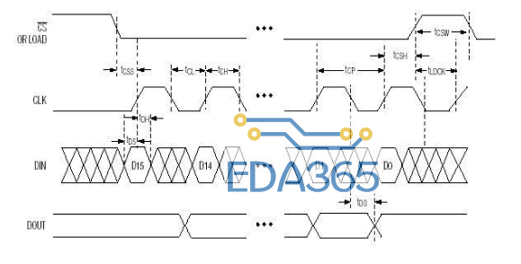
在运行之前,需要进行一次初始化,其行为是向某几个特定的地址写入特定的值。至少需要写入两个地址,第一个是0x0b,写入0x07表示扫描显示所有行。第二个是0x0c,写入1表示进入工作模式。
而后点阵上每一行都有其地址,如第一行是0x01到第八行是0x08,每次向固定行的地址写入一个8位二进制数即可在指定行上显示图案。
Linux可以通过访问sys/class/gpio下的一些文件,通过对这些文件的读写来实现对于GPIO的访问。
!/bin/bash
# DIN, CS, CLK的GPIO口位置
DIN=4
CS=3
CLK=2
# 一些文件路径
GPIO_BASE=/sys/class/gpio
GPIO_EXPORT=${GPIO_BASE}/export
GPIO_UNEXPORT=${GPIO_BASE}/unexport
BIN=(00000001 00000010 00000011 00000100 00000101 00000110 00000111 00001000)
# 生成指定GPIO引脚的文件夹位置
function GPIO(){
echo ${GPIO_BASE}/gpio$1
}
# 将某个引脚export到用户态
function GPIO_export(){
if [ -d `GPIO $1` ]; then
echo GPIO pin $1 found in folder.
else
echo $1 》 ${GPIO_EXPORT}
fi
}
# unexport某个引脚
function GPIO_unexport(){
if [ -d `GPIO $1` ]; then
echo $1 》 ${GPIO_UNEXPORT}
else
echo GPIO pin $1 not found.
fi
}
# 改变某个引脚的方向
function GPIO_direction(){
echo $2 》 `GPIO $1`/direction
}
# 改变某个引脚的值
function GPIO_set(){
echo $2 》 `GPIO $1`/value
}
# 改变DIN的值
function GPIO_DIN(){
GPIO_set $DIN $1
}
# 改变CS的值
function GPIO_CS(){
GPIO_set $CS $1
}
# 改变CLK的值
function GPIO_CLK(){
GPIO_set $CLK $1
}
# 向MAX7219发送一个byte的值
function Matrix_send_char(){
local i=1
for ((i=1;i《=8;i++)); do
chr=`expr substr $1 $i 1`
GPIO_DIN $chr
GPIO_CLK 1
GPIO_CLK 0
done
}
# 向MAX7219发送一次完整的信号
function Matrix_send_word(){
GPIO_CS 1
GPIO_CS 0
GPIO_CLK 0
Matrix_send_char $1
Matrix_send_char $2
GPIO_CS 1
}
# 初始化GPIO引脚
function GPIO_init(){
GPIO_export $DIN
GPIO_export $CS
GPIO_export $CLK
sleep 2
GPIO_direction $DIN out
GPIO_direction $CS out
GPIO_direction $CLK out
}
# 清除GPIO引脚
function GPIO_clear(){
GPIO_unexport $DIN
GPIO_unexport $CS
GPIO_unexport $CLK
}
# 在点阵上显示数据
function Matrix_render(){
local i=1
for ((i=0;i《8;i++)); do
echo $i $1
Matrix_send_word ${BIN[$i]} $1
shift
done
}
# 使用文件中的数据进行显示
function Matrix_render_file(){
local tmp=(`cat $1`)
Matrix_render “${tmp[@]}”
}
# 使用某个图案清屏
function Matrix_clear(){
local STR=(
00000000
01100110
11111111
11111111
11111111
01111110
00111100
00011000
)
Matrix_render “${STR[@]}”
}
# 初始化点阵
function Matrix_init(){
# 编码模式
Matrix_send_word 00001001 00000000
# 亮度
Matrix_send_word 00001010 00000011
# 扫描数码管个数
Matrix_send_word 00001011 00000111
# 工作模式
Matrix_send_word 00001100 00000001
# 初始化完毕后清屏显示默认图案
Matrix_clear
}
source matrix.sh
GPIO_init
Matrix_init
这里我使用了wiring库,非常容易上手。关键函数:digitalWrite()写GPIO;pinMode()设置GPIO方向;
需要注意的是它的管脚编号和树莓派不同。

#include 《wiringPi.h》
#include 《stdio.h》
#define uchar unsigned char
#define uint unsigned int
#define DecodeMode 0x09 //译码模式寄存器
#define Intensity 0x0a //亮度寄存器
#define ScanLimit 0x0b //扫描位数寄存器
#define ShutDown 0x0c //低功耗模式寄存器
#define DisplayTest 0x0f //显示测试寄存器
#define ShutdownMode 0x00 //低功耗方式
#define NormalOperation 0x01 //正常操作方式
#define ScanDigit 0x07 //扫描位数设置,显示8位数码管
#define DecodeDigit 0x00 //译码设置,8位均为非译码
#define IntensityGrade 0x0a //亮度级别设置
#define TestMode 0x01 //显示测试模式
#define TextEnd 0x00 //显示测试结束,恢复正常工作模式
#define DIN 8
#define CS 9
#define CLK 7
uchar buffer[8]={0x00,0x66,0xff,0xff,0xff,0xff,0x7e,0x3c,0x18};
void delay(uint t){
uint i;
while(t--)
for (i = 0; i 《 125; i++);
}
void sendChar(char ch){
char i, tmp;
for(i = 0; i 《 8; i++){
tmp = ch & 0x80;
if(tmp)
digitalWrite(DIN, HIGH);
else
digitalWrite(DIN, LOW);
ch = ch 《《 1;
digitalWrite(CLK, HIGH:);
digitalWrite(CLK, LOW);
}
}
void writeWord(char addr, char num){
digitalWrite(CS, HIGH);
digitalWrite(CS, LOW);
digitalWrite(CLK, LOW);
sendChar(addr);
sendChar(num);
digitalWrite(CS, HIGH);
}
void write(){
char i;
for(i = 0; i 《 8; i++){
printf(“%d %d\n”,i, buffer[i]);
writeWord(i + 1, buffer[i]);
}
}
void init(){
writeWord(0x09, 0x00);
writeWord(0x0a, 0x03);
writeWord(0x0b, 0x07);
writeWord(0x0c, 0x01);
}
int main(){
wiringPiSetup();
pinMode(DIN, OUTPUT);
pinMode(CS, OUTPUT);
pinMode(CLK, OUTPUT);
init();
wirte();
return 0;
}
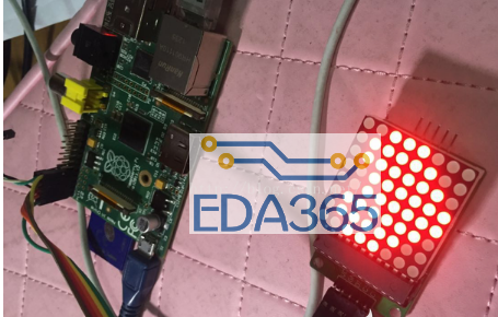
结果和前面一样。LED矩阵上显示了爱心。
初始化时首先分配给这个函数设备号,注册该设备,通过class注册使能够在/dev/目录下自动生成相应的设备文件,用户通过操作这个文件,来告诉内核怎么做。
由于是字符设备,所以对该文件的操作通过open,write,ioctl等函数,所以要把这个函数和底层的操作函数对应起来,这就要用到file_operation这个结构体来声明。
#include 《linux/kernel.h》
#include 《linux/module.h》
#include 《linux/device.h》
#include 《mach/platform.h》
#include 《linux/platform_device.h》
#include 《linux/types.h》
#include 《linux/fs.h》
#include 《linux/ioctl.h》
#include 《linux/cdev.h》
#include 《linux/delay.h》
#include 《linux/uaccess.h》
#include 《linux/init.h》
#include 《linux/gpio.h》
#include 《linux/string.h》
#include 《linux/tty.h》
#include 《linux/sched.h》
#define uchar unsigned char
#define uint unsigned int
#define DEVICE_NAME “Pi_Matrix”
#define DRIVER_NAME “pi_matrix”
//class声明内核模块驱动信息,是UDEV能够自动生成/dev下相应文件
static dev_t pi_matrix_devno; //设备号
static struct class *pi_matrix_class;
static struct cdev pi_matrix_class_dev;
struct gpio_chip *gpiochip;
#define DecodeMode 0x09 //译码模式寄存器
#define Intensity 0x0a //亮度寄存器
#define ScanLimit 0x0b //扫描位数寄存器
#define ShutDown 0x0c //低功耗模式寄存器
#define DisplayTest 0x0f //显示测试寄存器
#define ShutdownMode 0x00 //低功耗方式
#define NormalOperation 0x01 //正常操作方式
#define ScanDigit 0x07 //扫描位数设置,显示8位数码管
#define DecodeDigit 0x00 //译码设置,8位均为非译码
#define IntensityGrade 0x0a //亮度级别设置
#define TestMode 0x01 //显示测试模式
#define TextEnd 0x00 //显示测试结束,恢复正常工作模式
#define DIN 2
#define CS 3
#define CLK 4
uchar mybuffer[8] = {0x00,0x66,0xff,0xff,0xff,0x7e,0x3c,0x18};
uchar digits[][8]={
{0x1c, 0x22, 0x22, 0x22, 0x22, 0x22, 0x22, 0x1c}, // 0
{0x08, 0x18, 0x08, 0x08, 0x08, 0x08, 0x08, 0x1c}, // 1
{0x1c, 0x22, 0x22, 0x04, 0x08, 0x10, 0x20, 0x3e}, // 2
{0x1c, 0x22, 0x02, 0x0c, 0x02, 0x02, 0x22, 0x1c}, // 3
{0x04, 0x0c, 0x14, 0x14, 0x24, 0x1e, 0x04, 0x04}, // 4
{0x3e, 0x20, 0x20, 0x3c, 0x02, 0x02, 0x22, 0x1c}, // 5
{0x1c, 0x22, 0x20, 0x3c, 0x22, 0x22, 0x22, 0x1c}, // 6
{0x3e, 0x24, 0x04, 0x08, 0x08, 0x08, 0x08, 0x08}, // 7
{0x1c, 0x22, 0x22, 0x1c, 0x22, 0x22, 0x22, 0x1c}, // 8
{0x1c, 0x22, 0x22, 0x22, 0x1e, 0x02, 0x22, 0x1c}, // 9
};
void delay(uint t){
uint i;
while(t--)
for (i = 0; i 《 125; i++);
}
void sendChar(char ch){
char i, tmp;
for(i = 0; i 《 8; i++){
tmp = ch & 0x80;
if(tmp)
gpiochip-》set(gpiochip, DIN, 1);
else
gpiochip-》set(gpiochip, DIN, 0);
ch = ch 《《 1;
gpiochip-》set(gpiochip, CLK, 1);
gpiochip-》set(gpiochip, CLK, 0);
}
}
void writeWord(char addr, char num){
gpiochip-》set(gpiochip, CLK, 0);
gpiochip-》set(gpiochip, CS, 1);
gpiochip-》set(gpiochip, CS, 0);
sendChar(addr);
sendChar(num);
gpiochip-》set(gpiochip, CS, 1);
}
static int write_test(struct file *file, const char __user *buffer,
size_t count, loff_t *ppos){
char wbuf[100]={0};
copy_from_user(wbuf,buffer,100);
printk(“%s\n”,wbuf);
gpiochip-》set(gpiochip, CS, 1);
gpiochip-》set(gpiochip, CS, 0);
gpiochip-》set(gpiochip, CLK, 0);
return count;
}
static int pi_matrix_write(struct file *file, const char __user *buffer,
size_t count, loff_t *ppos){
char i;
char ch[1]={‘0’};
copy_from_user(ch,buffer,1);
printk(“%c ok\n”,ch[0]);
switch(ch[0]){
case ‘0’:
memcpy(mybuffer,digits[0],8);
break;
case ‘1’:
memcpy(mybuffer,digits[1],8);
break;
case ‘2’:
memcpy(mybuffer,digits[2],8);
break;
case ‘3’:
memcpy(mybuffer,digits[3],8);
break;
case ‘4’:
memcpy(mybuffer,digits[4],8);
break;
case ‘5’:
memcpy(mybuffer,digits[5],8);
break;
case ‘6’:
memcpy(mybuffer,digits[6],8);
break;
case ‘7’:
memcpy(mybuffer,digits[7],8);
break;
case ‘8’:
memcpy(mybuffer,digits[8],8);
break;
case ‘9’:
memcpy(mybuffer,digits[9],8);
break;
default:break;
}
for(i = 0; i 《 8; i++){
printk(“%d %d\n”,i, mybuffer[i]);
writeWord(i + 1, mybuffer[i]);
}
return count;
}
void init(void){
writeWord(0x09, 0x00);
writeWord(0x0a, 0x03);
writeWord(0x0b, 0x07);
writeWord(0x0c, 0x01);
}
//内核调用后的open操作
int open_flag=0;
static int pi_matrix_open(struct inode *inode, struct file *filp)
{
printk(“Open matrix ing!\n”);
if(open_flag ==0){
open_flag =1;
printk(“Open matrix success!\n”);
return 0;
}
else{
printk(“Matrix has opened!\n”);
}
return 0;
}
//内核调用后的release操作
static int pi_matrix_release(struct inode *inode,struct file *file){
printk(“Matrix has release!\n”);
return 0;
}
//file_operations使系统的open,write等函数指针指向我们所写的led_open等函数,
//这样系统才能够调用
static struct file_operations pi_matrix_dev_fops = {
.owner = THIS_MODULE,
.write = pi_matrix_write,
//.write = write_test,
.open = pi_matrix_open,
.release = pi_matrix_release,
};
static int is_right_chip(struct gpio_chip *chip, void *data)
{
if (strcmp(data, chip-》label) == 0)
return 1;
return 0;
}
//内核加载后的初始化函数。
static int __init pi_matrix_init(void)
{
struct device *dev;
int major; //自动分配主设备号
major = alloc_chrdev_region(&pi_matrix_devno,0,1,DRIVER_NAME);
cdev_init(&pi_matrix_class_dev, &pi_matrix_dev_fops);
major = cdev_add(&pi_matrix_class_dev,pi_matrix_devno,1);
//注册class
pi_matrix_class = class_create(THIS_MODULE,DRIVER_NAME);
dev = device_create(pi_matrix_class, NULL, pi_matrix_devno, NULL, DRIVER_NAME);
//通过这个函数把内核的GPIO操作和BCM2708的GPIO操作关联起来;
gpiochip = gpiochip_find(“bcm2708_gpio”, is_right_chip);
gpiochip-》direction_output(gpiochip, DIN, 1);
gpiochip-》direction_output(gpiochip, CLK, 1);
gpiochip-》direction_output(gpiochip, CS, 1);
init();
printk(“pi matrix init ok!\n”);
return 0;
}
//内核卸载后的销毁函数
void pi_matrix_exit(void)
{
gpio_free(DIN);
gpio_free(CS);
gpio_free(CLK);
device_destroy(pi_matrix_class,pi_matrix_devno);
class_destroy(pi_matrix_class);
cdev_del(&pi_matrix_class_dev);
unregister_chrdev_region(pi_matrix_devno, 1);
printk(“pi matrix exit ok!\n”);
}
module_init(pi_matrix_init);
module_exit(pi_matrix_exit);
MODULE_DESCRIPTION(“Rasp Matrix Driver”);
MODULE_AUTHOR(“HSQ”);
MODULE_LICENSE(“GPL”);

使用dmesg命令查看内核输出:
『本文转载自网络,版权归原作者所有,如有侵权请联系删除』


 热门文章
更多
热门文章
更多

 CC-Link现场总线及应用实例


 APP下载
APP下载 登录
登录


