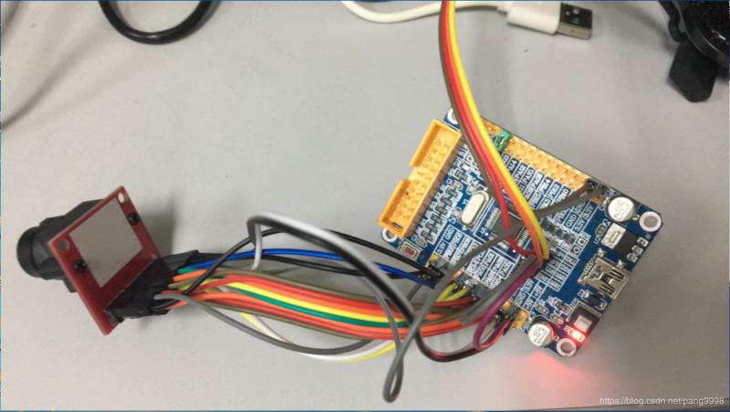
捣鼓了几天,终于点亮led了,那个欣慰啊。。。
至于建立工程模板,对于我这种小白来说确实不容易上手,捣鼓了好久,不是忘记添加.c文件,就是忘记加入头文件的路径(头文件的路径千万要是英文)。其实模板建立好之后,只需要编写两个文件夹(1)USER,用来编辑主函数的。(2)HADEWARE(硬件)用来配置相关硬件的,eg:包含led.c led.h 后面要用的话,直接在这里边调用就行了。
接下来就是led的点亮和蜂鸣器发出响声了。
对于led,首先上个电路图:
void LED_Init(void)
{
GPIO_InitTypeDef GPIO_InitStructure;
RCC_APB2PeriphClockCmd(RCC_APB2Periph_GPIOB|
RCC_APB2Periph_GPIOE, ENABLE); //使能 PB,PE 端口时钟
GPIO_InitStructure.GPIO_Pin = GPIO_Pin_5; //LED0-->PB.5 推挽输出
GPIO_InitStructure.GPIO_Mode = GPIO_Mode_Out_PP; //推挽输出
GPIO_InitStructure.GPIO_Speed = GPIO_Speed_50MHz;
GPIO_Init(GPIOB, &GPIO_InitStructure);
GPIO_SetBits(GPIOB,GPIO_Pin_5); //PB.5 输出高
GPIO_InitStructure.GPIO_Pin = GPIO_Pin_5; //LED1-->PE.5 推挽输出
GPIO_Init(GPIOE, &GPIO_InitStructure);
GPIO_SetBits(GPIOE,GPIO_Pin_5); /PE.5 输出高
}
要调好GPIO_InitTypeDef结构体中三个成员,传递参数进去完成初始化。
每个HADEWARE中的.c文件对应一个.h文件,再看#include "led.h",这是自己写的头文件
#ifndef __LED_H
#define __LED_H
#include "sys.h"
//LED 端口定义
#define LED0 PBout(5)// DS0
#define LED1 PEout(5)// DS1
void LED_Init(void);//初始化
#endif
这段代码里面最关键就是 2 个宏定义:
#define LED0 PBout(5)// DS0
#define LED1 PEout(5)// DS1
这样调用led更加方便,增加可读性。
重要的是要将led.c加到HADEWARE这个组里边:
#include "led.h"
#include "delay.h"
#include "sys.h"
//ALIENTEK 战舰 STM32 开发板实验 1
144
//跑马灯实验
int main(void)
{
delay_init(); //延时函数初始化
LED_Init(); //初始化与 LED 连接的硬件接口
while(1)
{ LED0=0;
LED1=1;
delay_ms(300); //延时 300ms
LED0=1;
LED1=0;
delay_ms(300); //延时 300ms
}
}
对于蜂鸣器,电路图没看懂,模数电没学过,电路也只学到11章,考了83分的渣渣,确实不知道NPN三极管怎么用,只是记住当 PB.8 输出高电平的时候,蜂鸣器将发声, 当 PB.8 输出低电平的时候,蜂鸣器停止发声。
#include "beep.h"
151
//初始化 PB8 为输出口 .并使能这个口的时钟
//LED IO 初始化
void BEEP_Init(void)
{
GPIO_InitTypeDef GPIO_InitStructure;
RCC_APB2PeriphClockCmd(RCC_APB2Periph_GPIOB, ENABLE);
//使能 GPIOB 端口时钟
GPIO_InitStructure.GPIO_Pin = GPIO_Pin_8; //BEEP-->GPIOB.8 端口配置
GPIO_InitStructure.GPIO_Mode = GPIO_Mode_Out_PP; //推挽输出
GPIO_InitStructure.GPIO_Speed = GPIO_Speed_50MHz; //速度为 50MHz
GPIO_Init(GPIOB, &GPIO_InitStructure); //根据参数初始化 GPIOB.8
GPIO_ResetBits(GPIOB,GPIO_Pin_8); //输出 0,关闭蜂鸣器输出
}
注意要使能相应的时钟端口
RCC_APB2PeriphClockCmd(RCC_APB2Periph_GPIOB, ENABLE);
同样,beep.h中
#ifndef __BEEP_H
#define __BEEP_H
#include "sys.h"
//蜂鸣器端口定义
#define BEEP PBout(8) // BEEP,蜂鸣器接口
void BEEP_Init(void); //初始化
#endif
主函数:
#include "sys.h"
#include "delay.h"
#include "led.h"
#include "beep.h"
//ALIENTEK 战舰 STM32 开发板实验 2
//蜂鸣器实验
int main(void)
{
delay_init(); //延时函数初始化
LED_Init(); //初始化与 LED 连接的硬件接口
BEEP_Init(); //初始化蜂鸣器端口
while(1)
{ LED0=0;
BEEP=0;
delay_ms(300);
LED0=1;
BEEP=1;
delay_ms(300);
}
『本文转载自网络,版权归原作者所有,如有侵权请联系删除』
 热门文章
更多


