Abstract
This report covers details about the design and part of the codes of the ultrasonic distance measurement and locating objects, which is part of a self-design robot project.
Distance detecting and bread pushing part
This part will discuss the distance test component, HCSR04 ultrasonic module, its application in our design and our working on bread push part.
1 Description of ultrasonic module HCSR04
The ultrasonic wave is used to measure the distance between the robot and the bread. By the reflecting the character of the ultrasonic wave, the distance between the ultrasonic module and the obstacle can be calculated by the formula
,
where L is the distance between bread and car, C is the speed of the ultrasonic wave in the air and T is the time difference of launching and receiving ultrasonic wave. However, error is inevitable by using this method because the robot is moving. When the module is working, the position of the car is not fixed. So, the measured time from the module is smaller than true time.
But in this experiment, the speed of the ultrasonic wave is much larger than the speed of the car thus the time between launching and receiving is so short that can be ignored.
In our design, the module chosen to launch and receive ultrasonic wave is HC-SR04. The picture of the module can be shown as below.
Figure 1.1. A picture of HCSR04 module
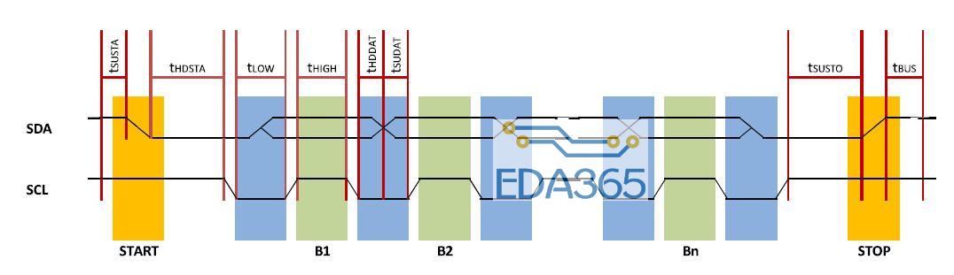
The module is IO trigger type. The triggering condition of the module is at least 10 microsecond high level signal. After being triggered, the module will launch eight 40 kHz square wave. When the module receive the back coming ultrasonic wave, it will get a continue high level as the output signal, the time for this high level is the time T mentioned in the last paragraph.
Figure 1.2. The time sequence of ultrasonic wave
The design processing picture is shown as below, the most important point should be mentioned is 30 ms in the processing. By the specification of the module, the minimum value of the triggering signal’s period is 60 ms. To avoid the next launching ultrasonic wave influences the echo of the last ultrasonic wave. The time between launching and receiving must smaller than 30 ms.
Figure 1.3. The diagram of he working logic of ultrasonic distance testing (display E means unable to measure the distance and shows error)
2 Bread locating procedure
This section will mainly describe how the bread is detected and pushed into the lake. At the beginning, our robot is moving along the fence which is facing the left side of the bread. The distance between the bread and the robot is measured by a ultrasonic equipment--HCSR04. The module emits a ultrasonic signal from the emitter. If the receiver can get the signal after some time, the distance can be measured through some mathematical method. As long as the distance is smaller than 20 cm, the robot will stop running ahead and turn left and moving straight ahead for one second, then it will turn right and moving straight ahead for one second, and then turn right and moving forward.
This means the robot changes its original position into the new position which is facing the front side of the bread. While the vehicle moving forward towards the bread, the ultrasonic equipment starts to measure a new distance between the bread and the vehicle. When the distance is smaller than 20cm, the vehicle will stop and the pushing rod will operate to push the bread into the lake and then it will moving backward. After this, the robot will turn left and finish the rest of the journey.
The code for ultrasonic distance measurement is shown below.
Figure 2.1. A screenshot of code fragment of ultrasonic distance measuring
One thing that should be mentioned is that the distance is set to 100 cm after the vehicle judges the distance is smaller than 20 cm. This is to disable the ultrasonic equipment so that the vehicle will not be disturbed by the environment during the turning. And we star the ultrasonic equipment again when the vehicle complete the turning.
3 Design and mechanical structure of the push rod
This section will mainly describe the self-designed bread-pushing rod and its operating principle. The process about how the robot pushes the rod in order to throw the bread into the lake.
The rod will stop as soon as the distance between the rod and bread is less than 20 centimeters. The battery will supply the energy to the micro-controller. In this project, mbed is used to perform this function. The energy will make the gear motor rotate, when the gear is activated, it will push the rod ahead and the rod will push the bread forward. And finally after a certain time (we estimated the time that the bread can be pushed away) the motor will rotate in the opposite direction and take back the rod.
Then some details in the process will be discussed. First is about the energy supply. At the beginning, the battery supply the energy to the mbed, but it is not strong enough to drive the motor. So between the mbed and motor we added an inverter to connect them. If a low voltage is given to the input of the inverter, it will output a higher voltage which is strong enough to make the gear rotate. Then it’s about how to push the rod by rotating the gear. The motor will make the gear rotate in clockwise after it accepts the command from the mbed. Then it will push rod ahead until for a certain time and after that the gear will rotate in the opposite direction to take back the rod. Besides, we place a rack which is in series with the rod and its insections are completely matched to the gear.
In the mechanical part, two plastic splines with teeth and a small DC-motor with a 5V supply voltage are the main components used.
There are some basic requirements. The first is the whole bread-pushing part must be easy to control, which means it should be able to be controlled based on simple code instructions, and the structure shall not get stuck itself during the motion process. The second is the part must be firm and reliable, which will bring more flexibility for other parts to error while it doesn’t do so itself. The third is the part shall be modifiable to a certain extent, so that the structure could be fixed or adjusted due to real situations and demands.
Figure 3.1. Figure 3.2.
A graphic of the bread pushing rod Picture of the bread pushing rod
At first, including the final version, there are three main possible solutions, namely, splines and a motor, a mechanical arm, a simple-structured single-use slingshot-like module. However, the mechanical arm is a bit too big for the scale of the body of the car, and hard to be programmed at the same time. Meanwhile, the slingshot structure is resistless to physical impact and vibrations, which will possibly result in high rate of spurious triggering during the advance. Thus, at last, the splines and a motor is chosen as the solution, due to its simplicity of programming with only one motor.
For the assembling of the structure, the supportive parts are self-made, due to the incompatibility of the default module. In practice, the self-made structure is proved to be efficient and good enough to stretch out and draw back.
『本文转载自网络,版权归原作者所有,如有侵权请联系删除』


 热门文章
更多
热门文章
更多

 五大标准轻松搞定4K超高清电视选购


 APP下载
APP下载 登录
登录


